
I started out by obviously taking the GBASP apart. There are many videos on the internet that can instruct you on how to disassemble the unit. It isn't really that hard and all you is a tri-wing screwdriver and small philips and flathead screwdrivers. We will start with the PCB already removed from the case.
For this tutorial the full list of things you will need:
*Tri-wing screwdriver
*philips and flathead screwdriver
*pliers
*razor knife
*wire cutter/stripper
*about 6 inches of wire (I use the wire from inside an NES controller cord)
*1/8" stereo audio jack
*soldering iron
*solder
*tinner
*dremel or hot blade(for cutting the case)
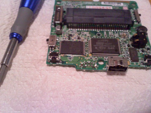
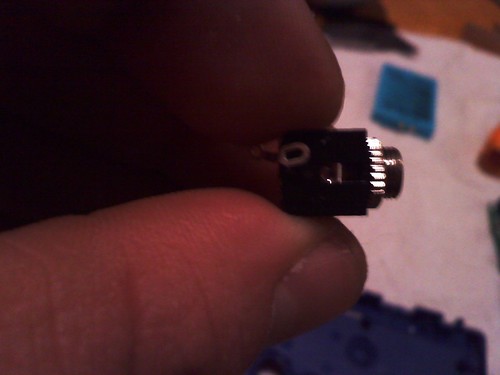
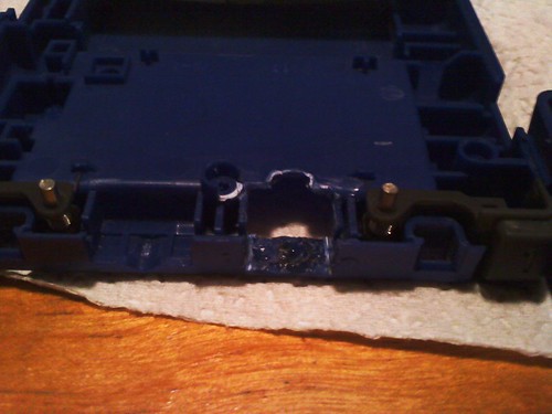
In this first picture you can see where I removed the link port. All you need to do to remove it is heat the solder points from the opposite side and use pliers to wiggle it back and forth until it comes loose. Be careful when you do this so that you do not snap the PCB.
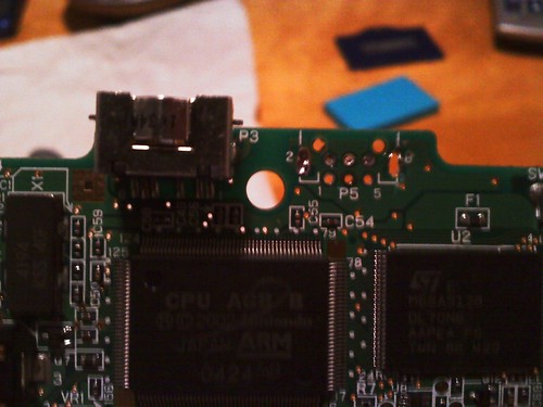
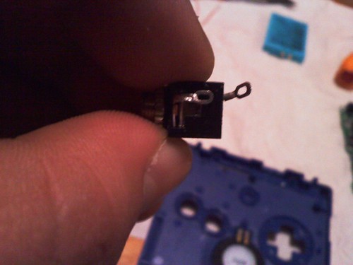
You can see here what it should look like after the link port is removed. Be sure to get rid of any excess solder as this is the area we will be mounting the audio jack.
We need to modify the sound jack to fit properly. This is the type of sound jack that I used.
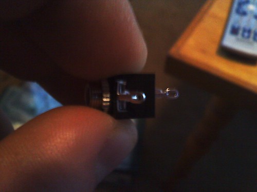
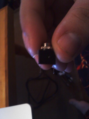
What we need to do is cut the tabs off of the sound jack and then move them all to one side so that they fit inside the SP. The best way to do this is to cut them off with your wire cutters. They are very easy to cut and then we will solder them back on the connections but not in the center. Be sure to mount them so they point out and away from the bottom to ensure proper fit. Like this...
Be sure to do them on the same side that I did. The jack will only fit into the sp one way.
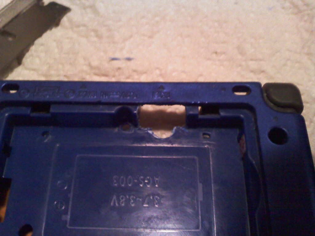
Now we go back to the top case of the SP, where the buttons go. We need to modify the hole where the link cable used to fit and make it fit the sound jack. We start by cutting with a razor blade or razor knife. We need to make it more square and bigger to house the audio jack. The best way is to make a cut and then check the size to the jack. making more cuts as needed.
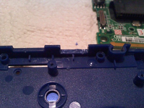
Then on the other piece... The bottom case we need to do the same but also on this one we need to use heat or a dremel to make the space a perfect fit for our audio jack. I used my soldering iron and a razor knife to do this part, only because at the time I did not own a dremel. First you make the cut in the bottom casing and use heat to make sure everything is level. Be very careful if you are using a soldering iron on this part as it is very easy to go too far and poke right through the case, ruining it. You also need to cut a notch in the screw mount as you can see in the picture. other wise the wiring will not fit.
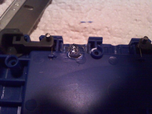
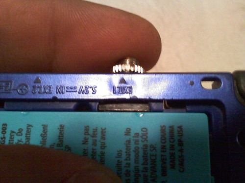
Now this part gets tricky. You need to cut into the battery compartment to gain that tiny little bit of extra room needed for this project. Use your soldering iron or dremel to SLOWLY cut into the compartment. just past the first ridge. and then make a little bit of a larger opening in the center for the tip of your audio plug to sit.
From inside the battery compartment....
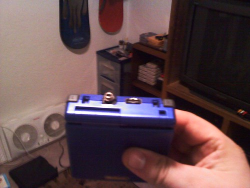
Now be sure to set your battery in there and confirm that it still sits correctly. We don't want any excess lumps or ridges from melting the plastic as they will make the battery fit incorrectly.
This is the time when I would do a test fit. put the PCB back into the unit and place your sound jack where it goes. Close it up and see if it fits. If it doesn't then you need to go back and shave your mounting holes a little bit more. Be careful not to over do it because the pressure and snugness is what is going to hold the audio jack in place when you are done.

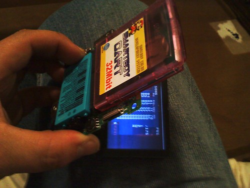
From inside the battery compartment with the battery installed.... You can see the jack sitting there, like I said there isn't much room inside the SP.
once you have a good fitting jack you can begin soldering. You need to attach wires to each of the tabs on the sound jack and then solder to the charging port contacts on the PCB. I used this diagram for reference, which can be found here

You are going to be soldering to the 2nd, 3rd, 4th, and 6th pins on this jack.
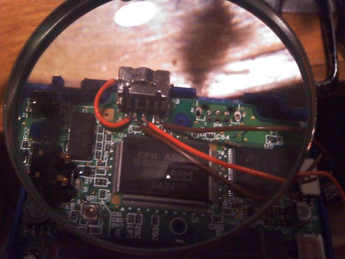
On the second pin you only need a short wire to go from the pin to the shield of the jack. This is the speaker and amp disable to make proper sound come through the headphones. Be sure to solder to the side of the jack otherwise the case will not close properly. The 3rd pin goes to the GRND on your jack (side), the 4th pin goes to the RT on your jack (middle) and the 6th pin goes to LT (last one).
Now you can set your jack in place being careful to not smash the wires. Be sure to put the jack in the same way you test fitted it. We moved the tabs on it for a reason, it only sits properly one way. carefully set everything back together and put in a screw or two. I would take this opportunity to test and make sure everything is working correctly. I did my testing while it was completely apart which was actually very difficult.
If everything works ok then go ahead and finish your reassembly and have fun with your SP. It is very nice to not have to keep track of that stupid little headphone adapter.


22 comments:
ohh great... I have been waiting for some one to do this!
Thanks capcomposer!
Awesome! I love this. You and Thetris do so many great things for the chiptune scene.
Just finished modding mine.
Anything I can do with a broken SP?
What happened? Did you break it while doing the mod?
Yeah...Totally my fault, though. I was being stupid. I have a really awful soldering iron and some of the solder got onto the CPU. I removed it, but now it won't turn on. Gives me an excuse to buy a new one, the screen was damaged and it was scratched up pretty bad. Gives me an excuse to buy a new soldering iron as well...
The one I modded in the tutorial is going to be for sale very soon. email me if you are interested. I am sorry to hear that yours broke. It really is a tight workspace in there isn't it!
This is freaking awesome. I'm pretty sure I wouldn't be able to do it myself though.
I could probly do that. Drop me an email for more details.
This has interested me, the only issue i can find with it is its size, but even then, bravo...its VERY good. Im just wondering if you considered using the sound jack from a gameboy colour or pocket, im not very good with electricals so would need your advice.
Thanks
What are you guys talking about?! Ask him what he plans to do when the battery runs out, he mutilated his charging port. There are a few devices that use that port too, usb adapters too. That's the worst idea I've seen so far for a headphone solution. Here's a easier way, bypass the internal speaker with a spliced wire (that interupts the speaker's circuit), and lead that to a small switch which will toggle the speaker, or will complete the circuit of an ordinary head phone jack, TADA, you haven't lost any ports, you still have the built in volume switch that works with the headphone jack, you can leave a long cord, etc. So,to clarify, all you need is a female end of an earphone jack (get from old walkman, or from male-to-female connector cord, etc.), a double wire, and a little switch. Another alternative, an earphone adapter is cheap to buy and easy to make.
I haven't tried to use any other audio jack in there but I know that NEX has done some amazing thins with the GBASP check it out here http://nex.gg8.se/modblog/2010/06/totally-kitted-out-gameboy-sp/. As for running straight from the speaker, that wouldn't really give you a clear quality sound. I like the idea but I guess I'll have to try it before I know for sure ;)
WTF?
http://www.ebay.co.uk/itm/Audio-Earphones-Headphones-Adapter-GBA-SP-New-/360321963738?pt=UK_Video_Games_Cables_and_Adaptors&hash=item53e4dcd6da#ht_1137wt_1139
easier aint it?
ROFL all that work and a simple cable already exists damn for not researching 1st =(
sorry, off topic, but how much would it cost if I sent in my old dmg for you to paint?
the other anonymous in here is an asshole
Hi there. Nice blog. You have shared useful information. Keep up the good work! This blog is really interesting and gives good details. soldering wires, soldering fluxes.
How do you charge it?
Are you guys retarded?? That's the link cable port, not the charger port ....
What kind of psychopath kills a Link Cable port?
I like the valuable information you provide in your articles. I'll bookmark your weblog and check again here regularly. I am quite certain I'll learn plenty of new stuff right here! Good luck for the next!
I visited various web sites except the audio feature for audio songs present at this web site is really fabulous.
Respect and that i have a neat offer: What Do House Renovations Cost house renovation loan
Post a Comment